對(duì)電子系統(tǒng)的有效熱設(shè)計(jì)Effective Thermal Design for Electronic Systems
Christian L. Belady, Hewlett-Packard Corporation
Angie Minichiello, Utah State University
緒論Introduction
過(guò)去,大家普遍認(rèn)為熱設(shè)計(jì)就是預(yù)測(cè)溫度并確保邊界值符合產(chǎn)品設(shè)計(jì)要求。但真正有效的熱設(shè)計(jì)卻不僅如此。我們相信在產(chǎn)品設(shè)計(jì)的早期構(gòu)思階段,熱設(shè)計(jì)人員不僅重要而且是最必不可少的。他們就是在這一階段提出預(yù)算。另外,熱設(shè)計(jì)人員的又一作用是排除那些僅為了方便或?yàn)榱私窈蟛榫慷O(shè)定的規(guī)范,從而確定真正的設(shè)計(jì)要求。In the past, the thermal designer's role was seen as one of predicting temperatures and ensuring that reliability limits are met for products. However, the role of an effective thermal designer is much more than that. We believe that thermal designers are both critical and most useful in the early conceptual stages of product design. This is where they provide the most "bang for the buck." In addition, the thermal designer's role is to challenge specifications that are often used merely for convenience or for legacy reasons, and to uncover the true requirements.
無(wú)論怎樣,系統(tǒng)熱設(shè)計(jì)的最終目的并不只是預(yù)測(cè)元件的溫度,而是要減少因?yàn)闊岬脑蚨斐傻漠a(chǎn)品設(shè)計(jì)失敗的風(fēng)險(xiǎn)。針對(duì)今天使用電源組的電子系統(tǒng)的固有特性,這種風(fēng)險(xiǎn)在折衷設(shè)計(jì)方法中十分顯著,由于無(wú)法預(yù)料熱及可靠性方面的問(wèn)題,這類方法通常不能按期完成項(xiàng)目設(shè)計(jì)。In any case, the ultimate goal of system thermal design is not the prediction of component temperatures, but rather the reduction of thermally associated risk to the product. This risk, inherent to today's power-packed electronic systems, is manifested by compromised designs that do not meet projected schedules due to unforeseen thermal and/or reliability issues. 圖1 就是這種說(shuō)法的很好證明。熱設(shè)計(jì)工程師從一開(kāi)始就應(yīng)該是整個(gè)設(shè)計(jì)工作的一部分,而不應(yīng)該等開(kāi)發(fā)過(guò)程到了后期才發(fā)揮作用。曲線圖主要為了說(shuō)明在設(shè)計(jì)初期所做的經(jīng)驗(yàn)性預(yù)測(cè)或者一些快速的筆算有時(shí)會(huì)比在設(shè)計(jì)后期才開(kāi)始進(jìn)行的所有CFD分析工作更有價(jià)值。Figure 1 illustrates this concept very well. Rather than wait until the later part of the development cycle (Figure 1a), the designer should be an integral part of the design right from the start (Figure 1b). The point of these curves is that your intuition or some quick hand calculations early in the design process is sometimes worth more than all of the CFD analysis work at the end of the design process.

圖1. 兩種方法在熱設(shè)計(jì)風(fēng)險(xiǎn)管理方面的對(duì)比圖Figure 1. A comparison of approaches used in risk management for thermal design.
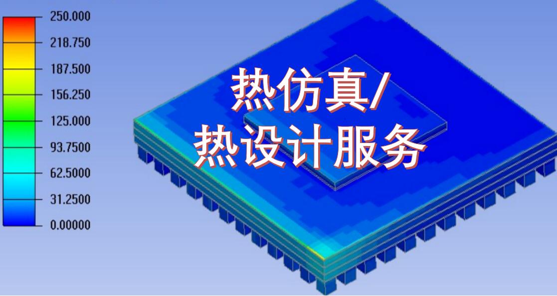
因而,熱設(shè)計(jì)就是工程師使用溫度和氣流預(yù)測(cè)幫助系統(tǒng)工程設(shè)計(jì)人員發(fā)現(xiàn)潛在風(fēng)險(xiǎn)區(qū)域的過(guò)程。(圖2 就是一個(gè)這樣的例子)。Thermal design, therefore, is the process by which engineers use temperature and airflow predictions to uncover potential risk areas for the system engineering team (an example of which is shown in Figure 2). 這里關(guān)鍵在于熱設(shè)計(jì)工程師是整個(gè)系統(tǒng)工程設(shè)計(jì)的一部分并且是以適時(shí)適當(dāng)?shù)木_方法開(kāi)發(fā)可行性解決方案的重要環(huán)節(jié)。The key point here is that the thermal design engineer is an integral part of the systems engineering approach and it is critical that the thermal designer develop feasible solutions in a timely and reasonably accurate manner. 熱設(shè)計(jì)的最終目標(biāo)是提供符合項(xiàng)目進(jìn)度及產(chǎn)品要求的優(yōu)化設(shè)計(jì)方案。Ultimately, the goal of the thermal design effort is to provide optimal designs that meet or exceed projected schedules and component requirements.

圖2. 一個(gè)典型的系統(tǒng)工程團(tuán)隊(duì)。其中關(guān)鍵是確定設(shè)計(jì)過(guò)程的重要環(huán)節(jié)并了解基本性能。Figure 2. A typical system engineering team. It is important to identify the key players in the design and to understand the basic features.
在這一過(guò)程中有很多工具來(lái)輔助熱設(shè)計(jì)工程師,包括熱傳遞相關(guān)性,流程網(wǎng)絡(luò)模型,計(jì)算流體力學(xué),以及實(shí)驗(yàn)測(cè)量技術(shù)。高效率綜合性的熱設(shè)計(jì)不一定是要選擇“最好”的工具,更重要的是以一種能在短時(shí)間內(nèi)獲得足夠方案的方式來(lái)使用這些工具以便系統(tǒng)工程設(shè)計(jì)團(tuán)隊(duì)能夠做出適時(shí)的設(shè)計(jì)決策。Many tools exist to assist thermal design engineers during this process, including heat transfer correlations, Flow Network Modeling (FNM), Computational Fluid Dynamics (CFD), and experimental measurement techniques. The key to efficient and comprehensive thermal design is not necessarily to choose the "best" tool for design, but rather to use the tools in a way that gets an adequate answer quickly so that the systems engineering team can make timely design decisions.
本文所述的是作者采用的一種熱設(shè)計(jì)方法來(lái)設(shè)計(jì)幾種企業(yè)型服務(wù)器。對(duì)于每一個(gè)案例,其結(jié)果都要滿足項(xiàng)目開(kāi)發(fā)的進(jìn)度同時(shí)不能改變熱解決方案的構(gòu)成,空氣推動(dòng)或機(jī)械封裝等。對(duì)如何實(shí)際應(yīng)用這一技術(shù)感興趣的讀者可以在ITHERM 2002學(xué)報(bào)中找到詳細(xì)的設(shè)計(jì)實(shí)例。This article presents the thermal design methodology used by the authors to design several enterprise servers. Relying upon this methodology, we were able to systematically reduce risk throughout the product design cycle for each of the servers. In each case. the result was that the designs met the project schedule while requiring no changes to component thermal solutions, air movers, or mechanical packaging. Readers interested in how this technique was actually applied will find a detailed design example published in the ITHERM 2002 proceedings [1].
熱設(shè)計(jì)方法論Thermal Design Methodology
熱設(shè)計(jì)方法論的框架是在1997年由Biber和Belady首先提出的,后來(lái)發(fā)展成為我們今天所說(shuō)的“增強(qiáng)的產(chǎn)品設(shè)計(jì)流程”。The framework of this thermal design methodology was first introduced in 1997 by Biber & Belady and later evolved into what we now call the "Enhanced Product Design Cycle"[2]. 根據(jù)這種方法,開(kāi)發(fā)周期由三個(gè)階段組成:設(shè)計(jì)規(guī)劃,細(xì)節(jié)設(shè)計(jì)和硬件測(cè)試。在每一階段,都要使用最適合最便捷的熱設(shè)計(jì)工具,如圖3所示。According to this method, the development cycle consists of three distinct phases: Concept Development, Detailed Design, and Hardware Test. During each phase, the most applicable and expedient thermal design tools are used, as proposed in Figure 3. 因此,這種方法采用一種“流動(dòng)的”設(shè)計(jì)過(guò)程,在第一階段對(duì)使用工具的預(yù)測(cè)會(huì)與下一設(shè)計(jì)階段的預(yù)測(cè)作比較并采用新的工具。用這種方法,每步設(shè)計(jì)都會(huì)驗(yàn)證,而且熱設(shè)計(jì)工程師可以對(duì)其早期工作中的假設(shè)和經(jīng)驗(yàn)進(jìn)行測(cè)試。Thus, the methodology promotes a "fluid" process in which the predictions of tools used in the first phase are compared with subsequent predictions as the design enters the next phase and new tools are adopted. In this way, each step is validated and the thermal designers can test their intuition and the assumptions of their earlier work.

圖3. 增強(qiáng)產(chǎn)品的開(kāi)發(fā)流程Figure 3. Enhanced product development cycle.
設(shè)計(jì)規(guī)劃Concept Development
設(shè)計(jì)規(guī)劃階段是產(chǎn)品開(kāi)發(fā)流程的最初階段。在這一階段初期,產(chǎn)品規(guī)劃還不成熟。這一階段的特點(diǎn)是由于系統(tǒng)工程團(tuán)隊(duì)的代表們不斷討論產(chǎn)品要求改進(jìn)設(shè)計(jì)思想使得產(chǎn)品布局和要求不斷改變。The Concept Development Phase is the initial stage in the product design cycle. At the start of this phase, the product concept is in its infancy. This phase is characterized by rapidly changing product layouts and requirements as representatives from the systems engineering team meet to discuss requirements and to develop new ideas. 在此,熱設(shè)計(jì)工程師的目的是徹底分析各個(gè)環(huán)節(jié),同時(shí)迅速提出切實(shí)的改進(jìn)設(shè)計(jì)方案。這一階段就是要確定一個(gè)能夠滿足或超出所有設(shè)計(jì)要求的產(chǎn)品設(shè)計(jì)格局。當(dāng)這個(gè)階段快要完成時(shí),熱設(shè)計(jì)工程師應(yīng)完成以下工作:Here, the goal of the thermal designer is to analyze scenarios thoroughly, yet rapidly as well as offer design suggestions for improvement in real time. This phase concludes in a single product layout that meets or exceeds all requirements. At the conclusion of this phase, the thermal designer has:
- 完成初級(jí)的可支持單位功耗的封裝設(shè)計(jì)(從板級(jí)到機(jī)柜)。Completed a preliminary packaging concept (board through cabinet level) that can support the power dissipation of the unit.
- 完成初步的空氣動(dòng)力選擇,包括尺寸,數(shù)量,位置以及方向。Completed preliminary air-mover selection, including size, number, location, and orientation.
- 確定重要元件的散熱器尺寸和安放位置以確保有足夠的空間。Sized and placed critical component heat sinks to ensure that adequate volume is available.
- 估計(jì)流過(guò)產(chǎn)品的所有排氣路徑的空氣溫度。Estimated the air temperature rises through all exhaust paths of the product.
- 確定有熱風(fēng)險(xiǎn)的區(qū)域并提出必要的減小風(fēng)險(xiǎn)的改進(jìn)設(shè)計(jì)建議。Identified areas of thermal risk and proposed design improvements necessary to mitigate these risks.
規(guī)劃發(fā)展階段的熱工具:一個(gè)最容易被忽視但卻十分強(qiáng)大的工具就是老練的熱設(shè)計(jì)工程師敏銳的設(shè)計(jì)直覺(jué)。Concept Development Phase Thermal Tools: One of the most overlooked yet powerful tools that the seasoned thermal designer has is his or her intuition. 熱設(shè)計(jì)工程師在很短時(shí)間內(nèi)就可能依以往的經(jīng)驗(yàn)對(duì)當(dāng)前問(wèn)題作出快速反應(yīng),也許這種第一反應(yīng)不夠準(zhǔn)確,但這就夠好了。In a matter of seconds, the thermal designer can leverage past experiences to provide a "gut" response that may not be accurate but is, in fact, good enough. 這些經(jīng)驗(yàn)可以對(duì)各種設(shè)計(jì)規(guī)劃進(jìn)行實(shí)時(shí)的調(diào)整,為系統(tǒng)工程師提供難以置信的“預(yù)算控制”。These "gut" responses allow real-time sorting of many concepts and offer incredible "bang for the buck" for system engineering teams. In order to do this, the thermal designer needs to develop a sense of intuition, which necessitates constant validation by using tools.
Based upon their ease of use, quick solve times, and limited required input data (usually geometry and fluid data only), the common tools used in the concept phase are generalized correlations for heat transfer and fluid flow (i.e., hand calculations), spreadsheets (such as heatsink design optimizers), and Flow Network Modeling (FNM) techniques. FNM tools can be as simple as solving a network of resistances (both thermal and fluid) either with hand calculations and spreadsheets, or by using commercially available tools. Details of FNM techniques can be found in [1].
FNM techniques are easy to master as long as the 2D air flow paths can be clearly defined. In some cases, 2D flow path prediction is not possible and advanced techniques such as CFD or testing may be warranted. Regardless of whether FNM-specific software or spreadsheets are used, solutions are gained within seconds. This is extremely important in this phase of the development cycle.
Detailed Design
Once a single layout has been agreed upon, the Detailed Design phase of work begins in earnest. The thermal designer must now focus on identified areas of thermal risk within the product. Here, thermal analyses become more detailed (and time consuming), while results become more refined. Experimental measurement and construction of mockups of system-critical areas may be required for input into models or to gain information concerning product areas that are difficult to model. The ultimate goal of the thermal designer is to dig deeply into critical areas and to offer design suggestions, which can facilitate an optimal product design that meets or exceeds the project schedule and reliability goals.
Detailed Design Phase Thermal Tools: Tools commonly used in the electronics industry for detailed thermal design are Computational Fluid Dynamics (CFD) and Finite Element Analysis (FEA) solvers. Typically, these types of analyses require longer setup/solve times and more detailed input data. Three dimensional (3D) modeling or simplification of existing 3D Computer Aided Design (CAD) models may be required. User experience is required for the most accurate results. Furthermore, based upon system size and complexity, empirical sub-system flow resistance data may be acquired using flow-bench testing of fans, heat sinks and subsystems. CFD solvers marketed for the electronics industry afford designers the ability to perform heat transfer calculations in addition to fluid flow solutions. FEA analyses may be required to solve for component, interconnect, or board temperatures once global airflow rates or heat transfer coefficients are calculated.
Hardware Test
Once product prototypes are available, the Hardware Test phase begins. The goal of the thermal designer here is to measure critical components and areas of risk experimentally within the product to verify the design. At this point, there should be no surprises. Additionally, measurements are compared to estimates in order to "calibrate" or fine tune earlier models (calibrated models can be used in future studies). These comparisons are used to determine the accuracy of initial predictions and to help the designer develop "thermal intuition".
Hardware Test Phase Thermal Tools: While the most common tool for temperature measurement is certainly the thermocouple, additional tools, such as thermistors, resistance temperature detectors (RTDs), thermochromic liquid crystals, thermopiles, and infrared imaging techniques, are also available. Air velocity measurement is also valuable during this phase. Classic hot wire anemometers provide the most precise measurements (i.e., speed and direction), but can be fragile, difficult to calibrate, and expensive. Newer "rugged" hot wire multi-channel probes that measure speed and temperature are also available.
Methodology Summary
Figure 4 shows the impact the thermal engineer can make on the product. The further to the left that issues and solutions are identified, the more positive the impact upon the product and product schedule. At some point, the thermal engineer can have a negative impact (further to the right) by identifying problems late and requesting changes when the design has become relatively fixed. This is not where the thermal engineer wants to be. It is our contention the salary/raises afforded thermal engineers will follow this curve as well.

Figure 4. The thermal designer's impact on the product schedule.
Risk Management
Figure 5 illustrates the importance of using the right tool at the right time. The red curve represents the risk level throughout the development cycle if only intuition, simple hand calculations and spreadsheets are used prior to testing the hardware. The green curve shows the risk level throughout the development cycle if a complete suite of tools is used. Note, in this case, the methodology approaches the ideal risk curve as a result of using the modeling technique that matches the design's fluidity.
The key to minimizing the risk early is to use the tool that gets a reasonable answer most quickly. In addition, Figure 5 also shows that in the case of the green curve, the same risk level is reached in about a quarter of the time shown for the red curve. This implies that an engineer using the technique proposed can be four times more productive.

Figure 5. Using the right tools for risk management.
Conclusions
The focus of the proposed methodology is the systematic reduction of product risk through the careful application of available thermal design tools and techniques. When applied to the design of the servers, the methodology has shown to provide adequate and timely results. The key advantages of the proposed methodology are that it:
- Enables a low risk design, which meets project schedules without necessarily having exact temperature/airflow predictions.
- Utilizes an optimum combination of design tools to increase productivity and reduce design time.
- Exhibits no a priori preference for a given design tool, and emphasizes the use of whichever tool makes sense at the time. The key is to get the right data to make the right design decisions.
Christian Belady, P.E.
Hewlett Packard Company
High Performance Systems Laboratory (HPSL)
Angie Minichiello, P.E.
Space Dynamics Laboratory / Utah Sate University
References
1.Minichiello, A. and Belady, C., " Thermal Design Methodology for Electronic Systems", Proceedings of the ITHERM 2002 Conference, May 2002, pp. 696-704.
2.Biber, C. and Belady, C., "Pressure Drop Prediction for Heat Sinks: What Is the Best Method?", Proceedings of InterPACK '97 Conference, Mauna Lani, Hawaii, EEP-VOL-19-2, ASME, 1997, pp. 1829 -1835.
標(biāo)簽: 點(diǎn)擊: 評(píng)論: